PrinterWorks
A collection of PCB's developed in collaboration with Clockworks for building custom 3D Printers
PrinterWorks
Our 3D printer mods and PCB's.
RBARF and the rack power board PDU20V have pages of their own.
CANDU V1.1
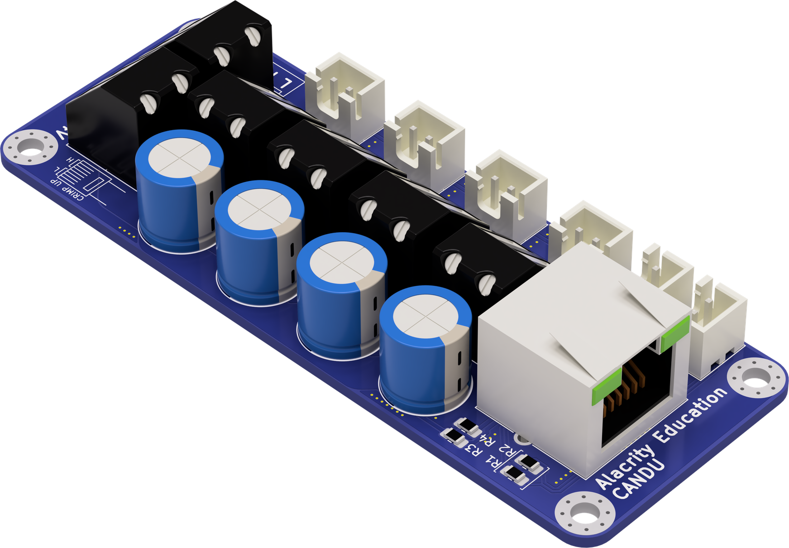
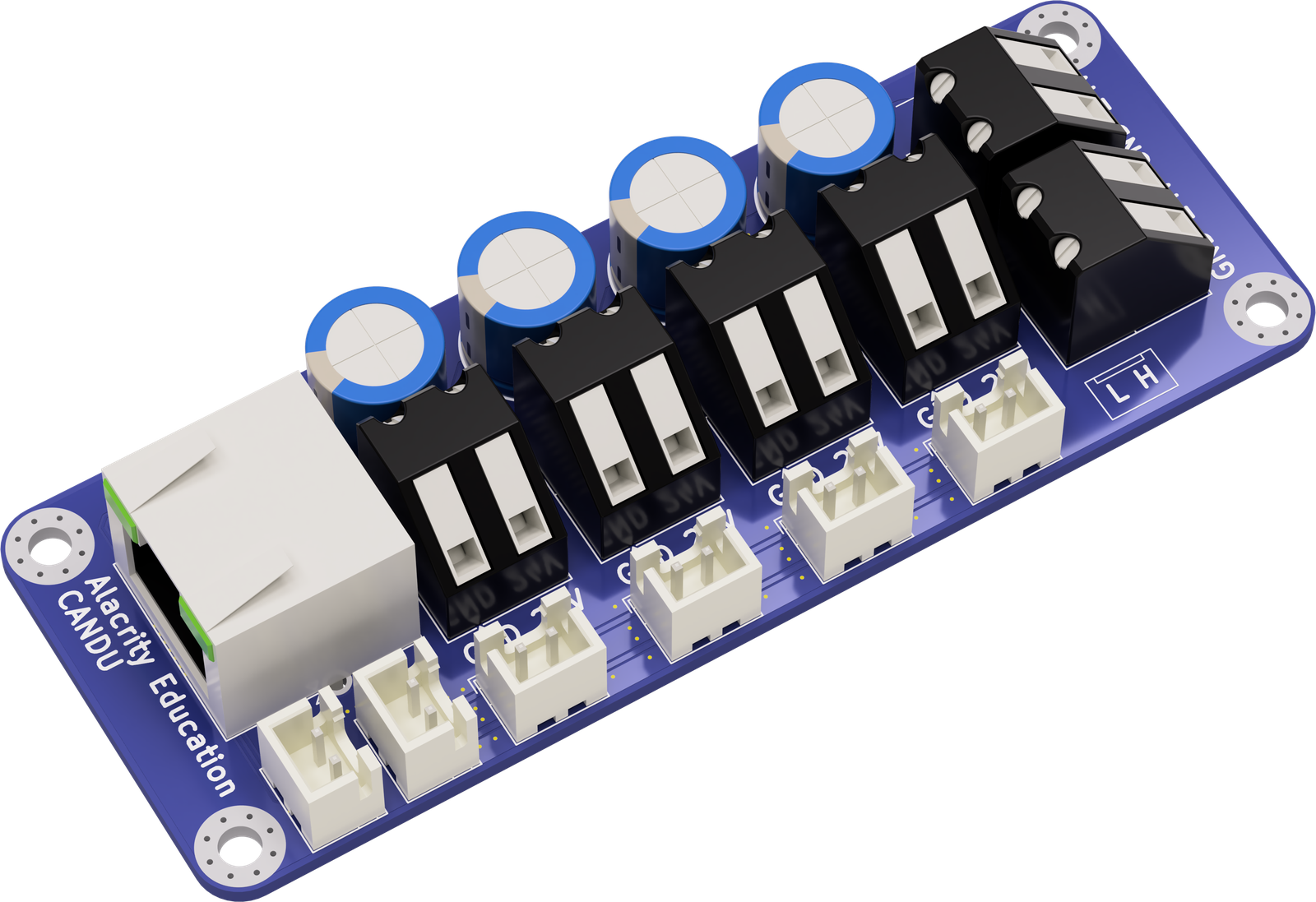
CAN DistribUtor is a board that distributes CAN and 24V power to multiple toolheads or CAN devices, like ERCF MMUs.
The board has no active parts: every CAN connector is on the same bus, and every power terminal is on the same 24V rail.
 |
 |
 |
|---|
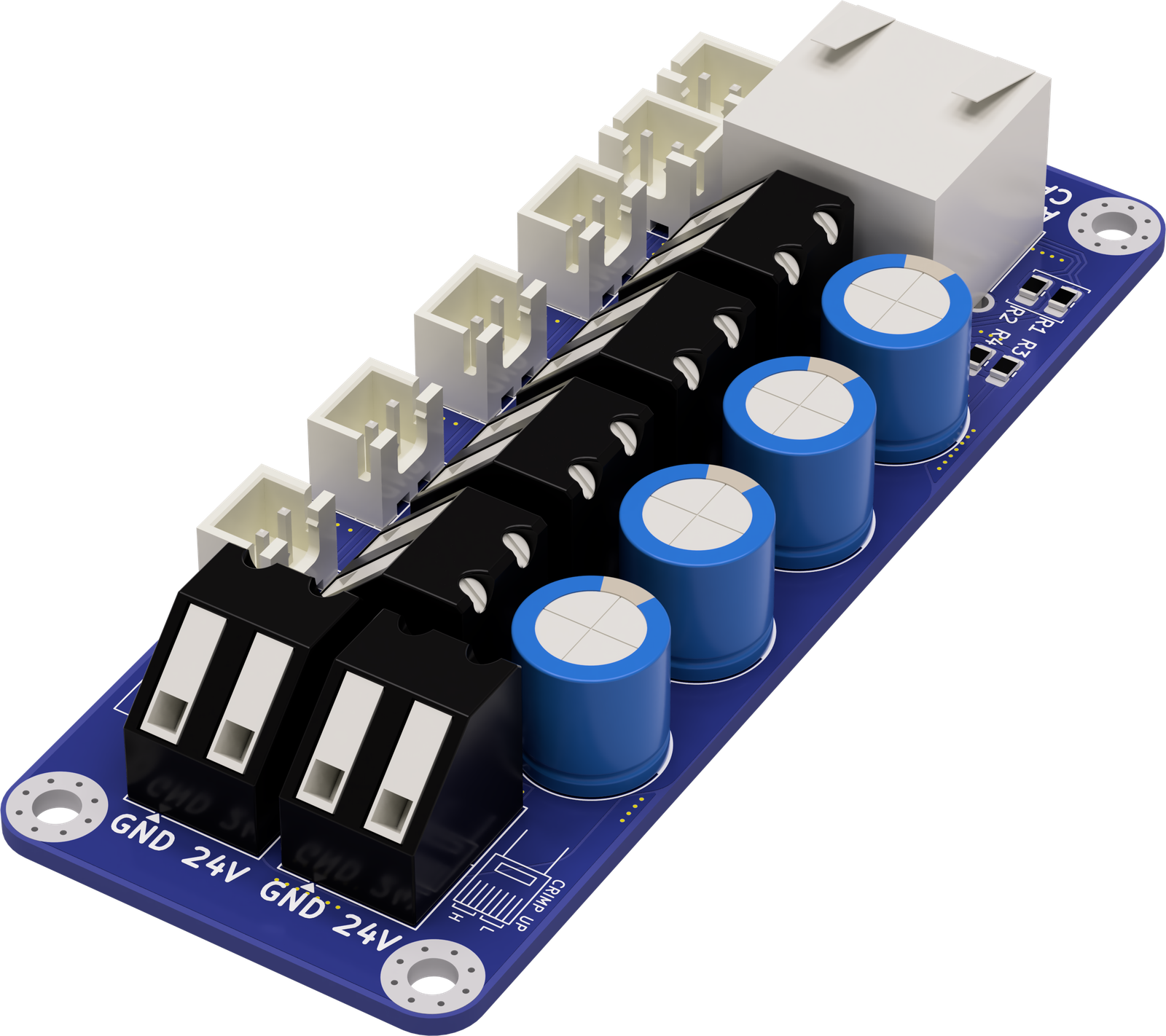
Ports
- 1x Power Uplink
- 1x CAN Uplink, by RJ45 connector
- 4x CAN+Power Downlinks to end devices
- 2x Extra CAN Downlinks
- 1x Power Downlink
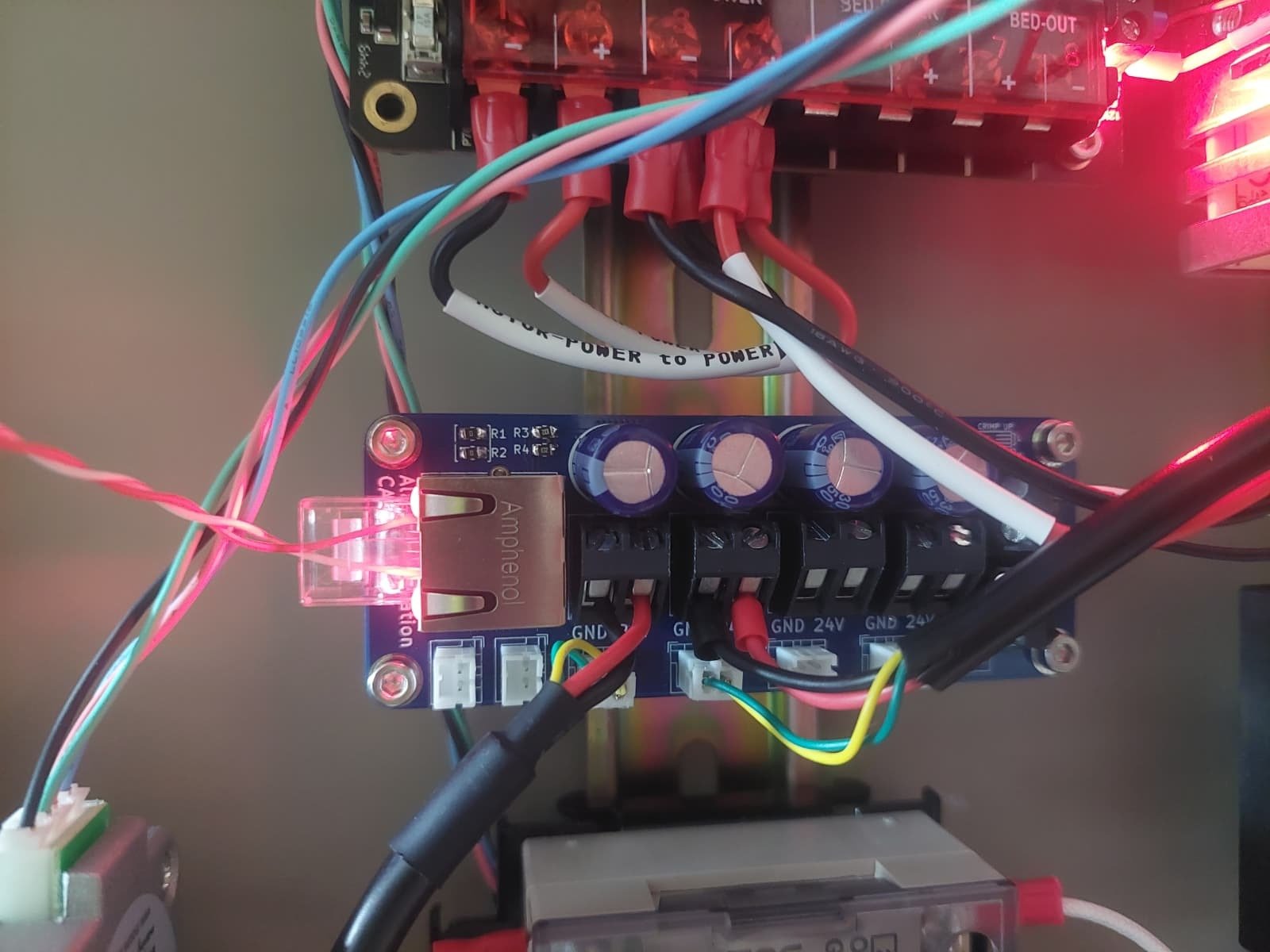
- Power indicator LED: the LEDs in the RJ45 jack light up when the board has 24V.
The board is self-documenting: crimping instructions and pinouts are printed on the silkscreen.
RJ45 pinout
4 pins of the RJ45 are mapped to CAN H, and the other 4 to CAN L.
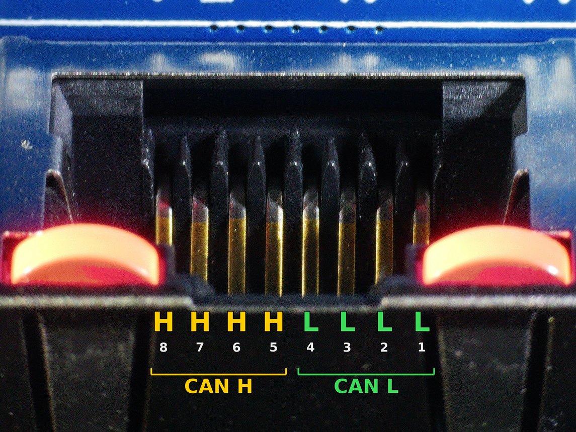
Swapping CAN H and L on the RJ45
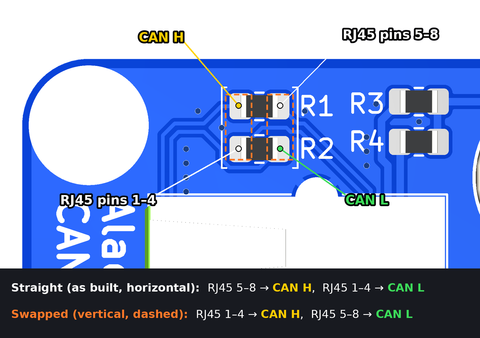
The CAN L-H pair coming from the RJ45 jack can be swapped by rotating the resistor placement near the jack by 90 degrees. R1 and R2 are two 0 Ω links whose four pads form a square:
- Straight (as built): both links horizontal. RJ45 pins 5-8 go to CAN H, pins 1-4 to CAN L.
- Swapped: both links vertical, on the dashed outlines. RJ45 pins 1-4 go to CAN H, pins 5-8 to CAN L.
The swap only affects the RJ45 uplink.
Notes
- The CAN bus needs a 120 Ω terminator at each end. The board has none, so terminate at the host and at the last device.
- If using long cables to the 2-4 devices, terminate at two devices instead of at the host. In this case, make sure the CANDU-Host cable is short.
- Four 330 µF high-quality capacitors (C1-C4) buffer the 24V rail.
- M3 mounting holes are connected to GND.
INDXWorx V0.1
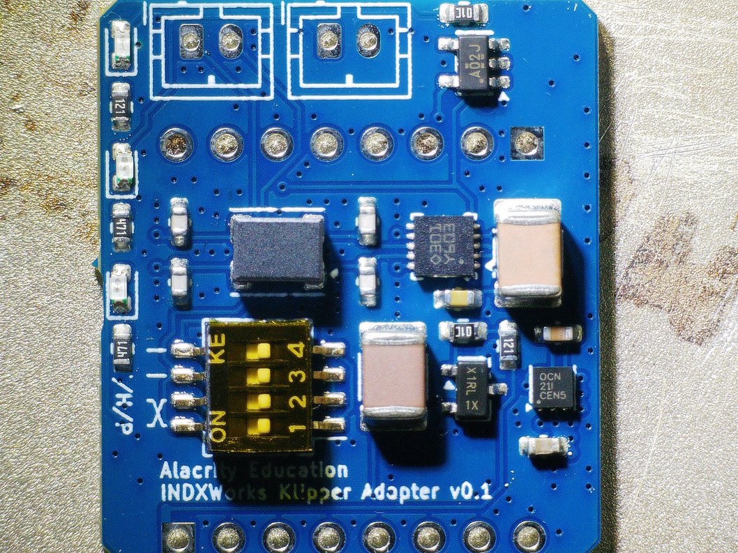
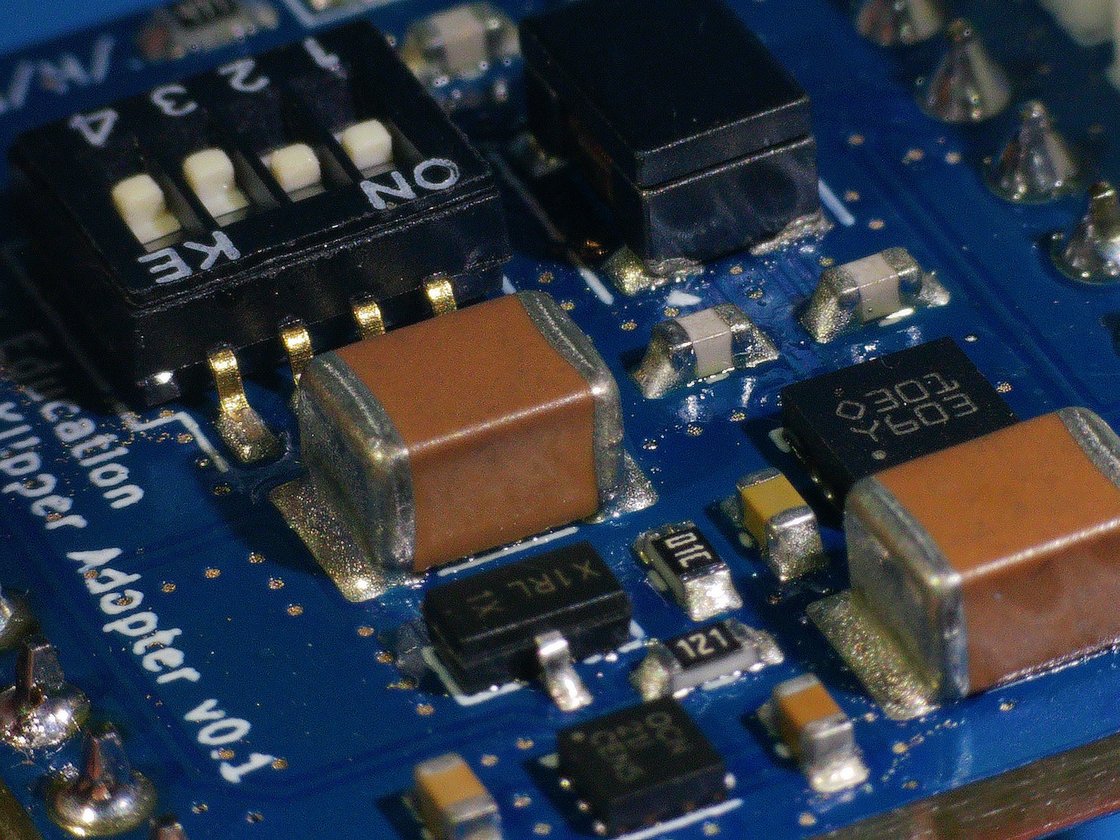
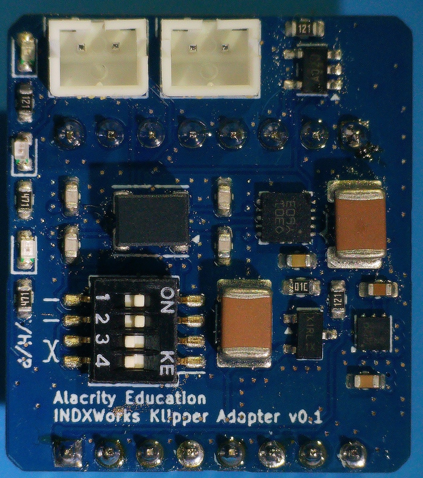
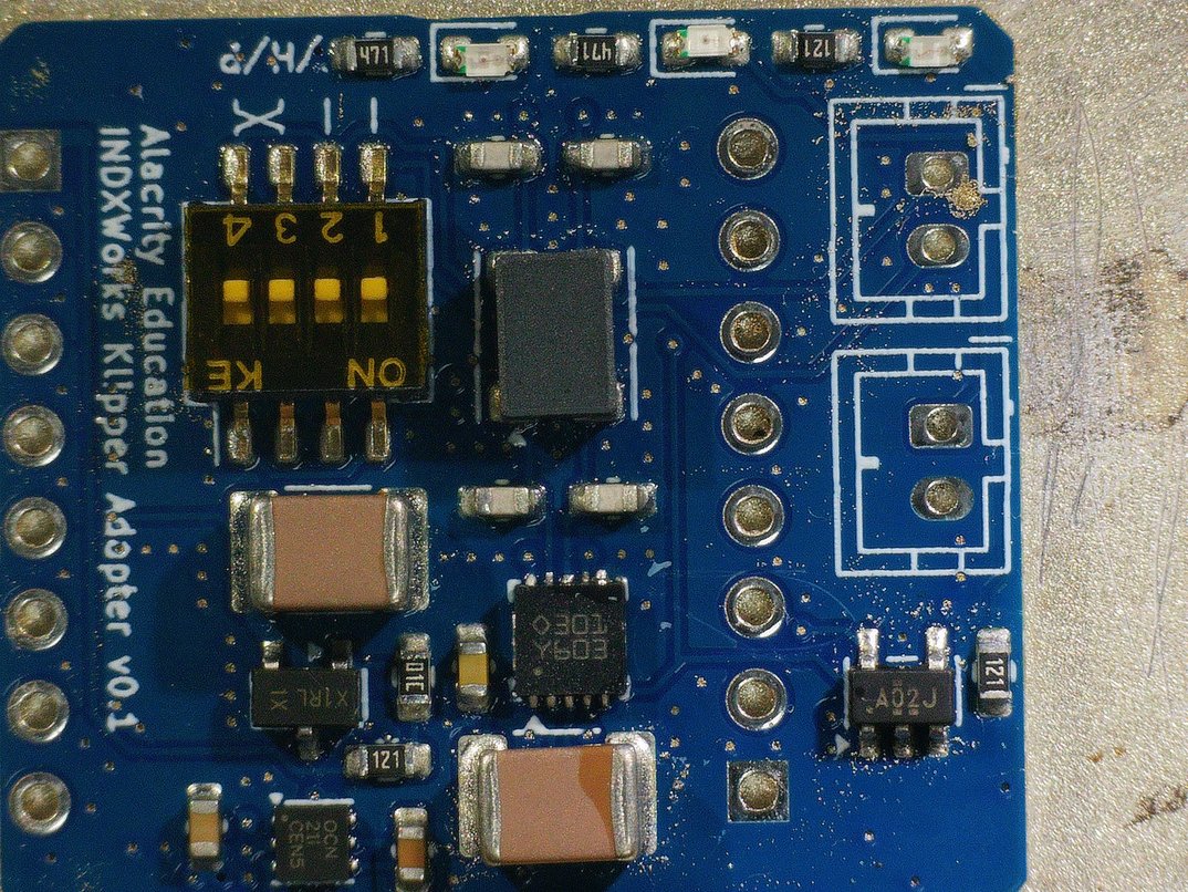
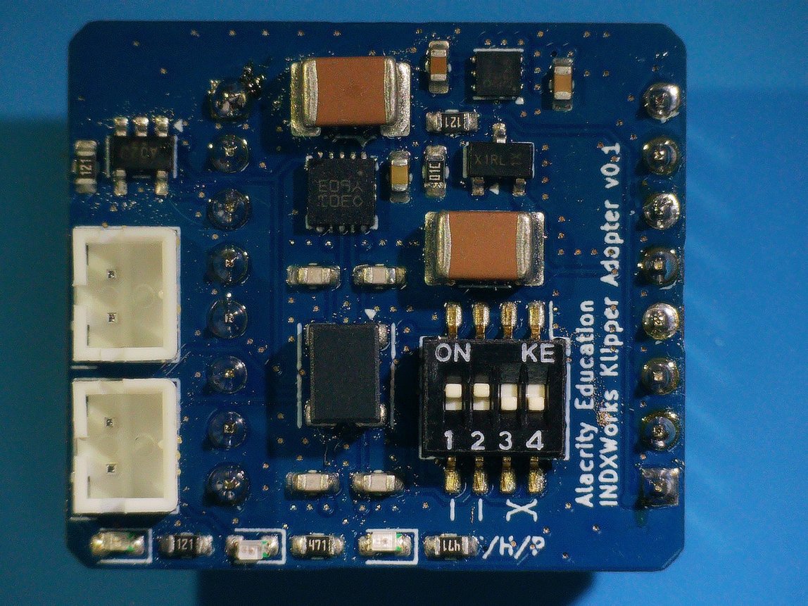
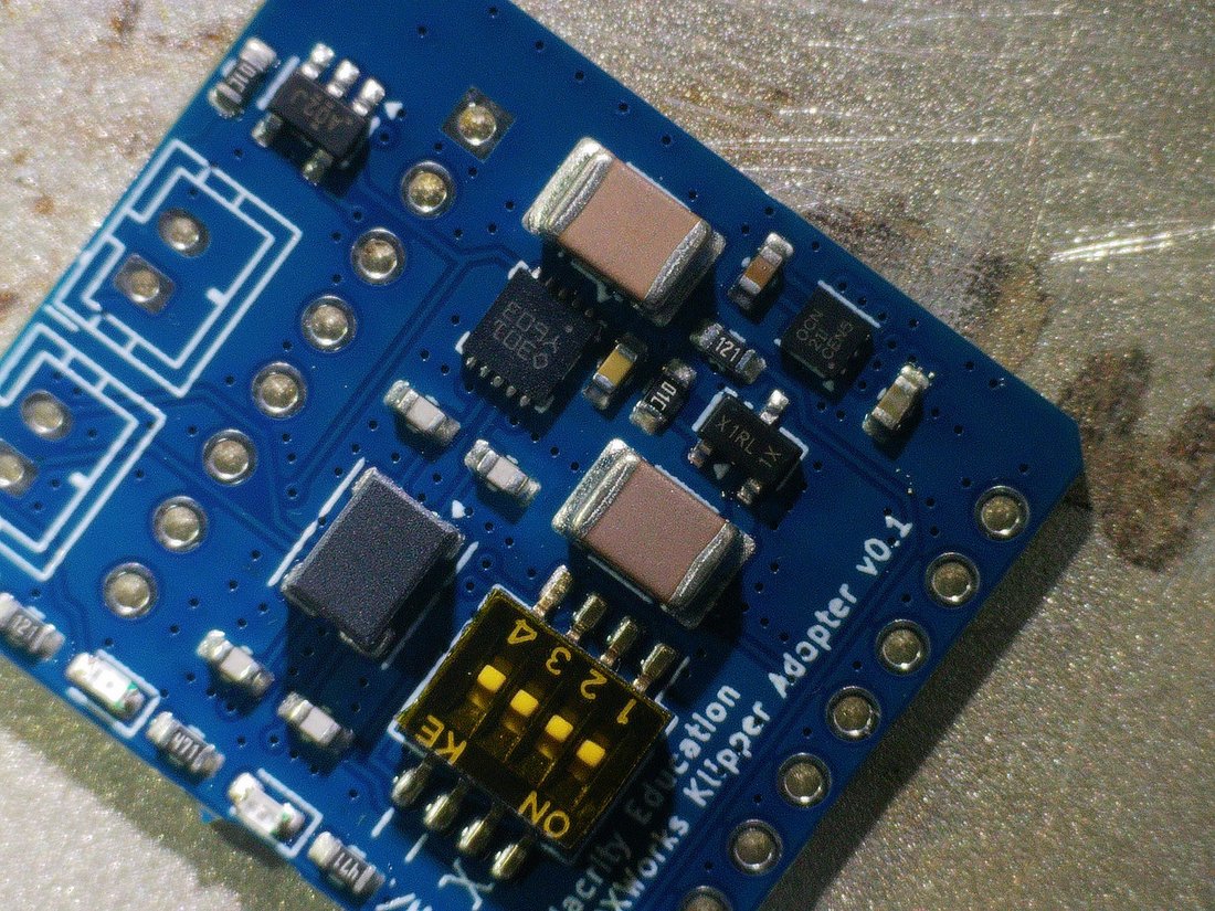
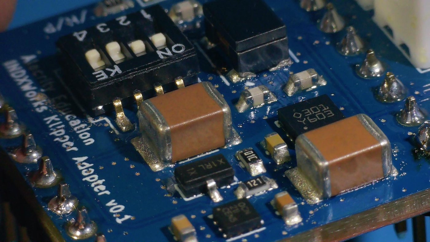
An adapter that connects the Bondtech INDX Prusa head to a Klipper printer. It is designed to plug into the BTT Octopus mainboard.
The head talks RS485. The board carries an ST STR485, a very high quality RS485 transceiver, and gives the head switchable 5V power.
 |
 |
|---|
Features
- RS485 through the ST STR485 transceiver, with 120 Ω termination on the board.
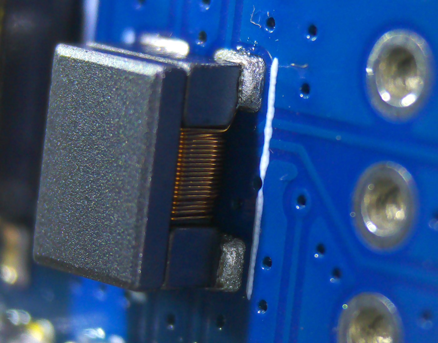
- Very good ESD protection and common-mode rejection on the RS485 line: a common-mode choke (Murata DLW43SH), an ESD protection diode (NUP2105L) and 100 pF C0G filter capacitors.
- Clean supplies: a TI TPS60151 flying-capacitor charge pump makes a clean 5V from the Octopus 3.3V, and an MCP1825 LDO makes the board's own 3.3V.
- Switchable 5V head power, through a P-MOSFET.
- LEDs for board power, 5V head power and RS485 activity.
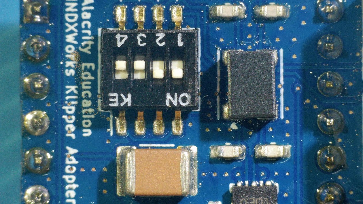
- RS485 line swapper: a DIP switch poka-yoke, so the two RS485 lines can be swapped without re-crimping the cable.
Connections
Octopus
The board plugs into the Octopus WiFi socket. It uses these Octopus pins:
| Octopus pin | Function |
|---|---|
| PD5 (TX3) | RS485 transmit |
| PD6 (RX3) | RS485 receive |
| PD7 | RS485 driver enable (DE) |
| PD10 | RS485 receiver enable (/RE, active low) |
| PG7 | Head 5V switch: on by default, drive high to switch the head off |
Head
space 797x900
1 box 85,30 290,185 blue
1 pin 150,88 blue label="1"
1 pin 215,88 blue label="2"
2 box 305,30 495,185 red
2 pin 365,88 red label="1"
2 pin 428,88 red label="2"
  tri 188,20 down yellow
  tri 400,20 down yellow
  tri 600,22 down yellow
  text 660,28 "tab side" size=20 yellow anchor=start
- RS485 — pin 1:
+(A), pin 2:−(B) - 5V_SW (head power) — pin 1: 5 V, pin 2: GND
RS485 line swapper
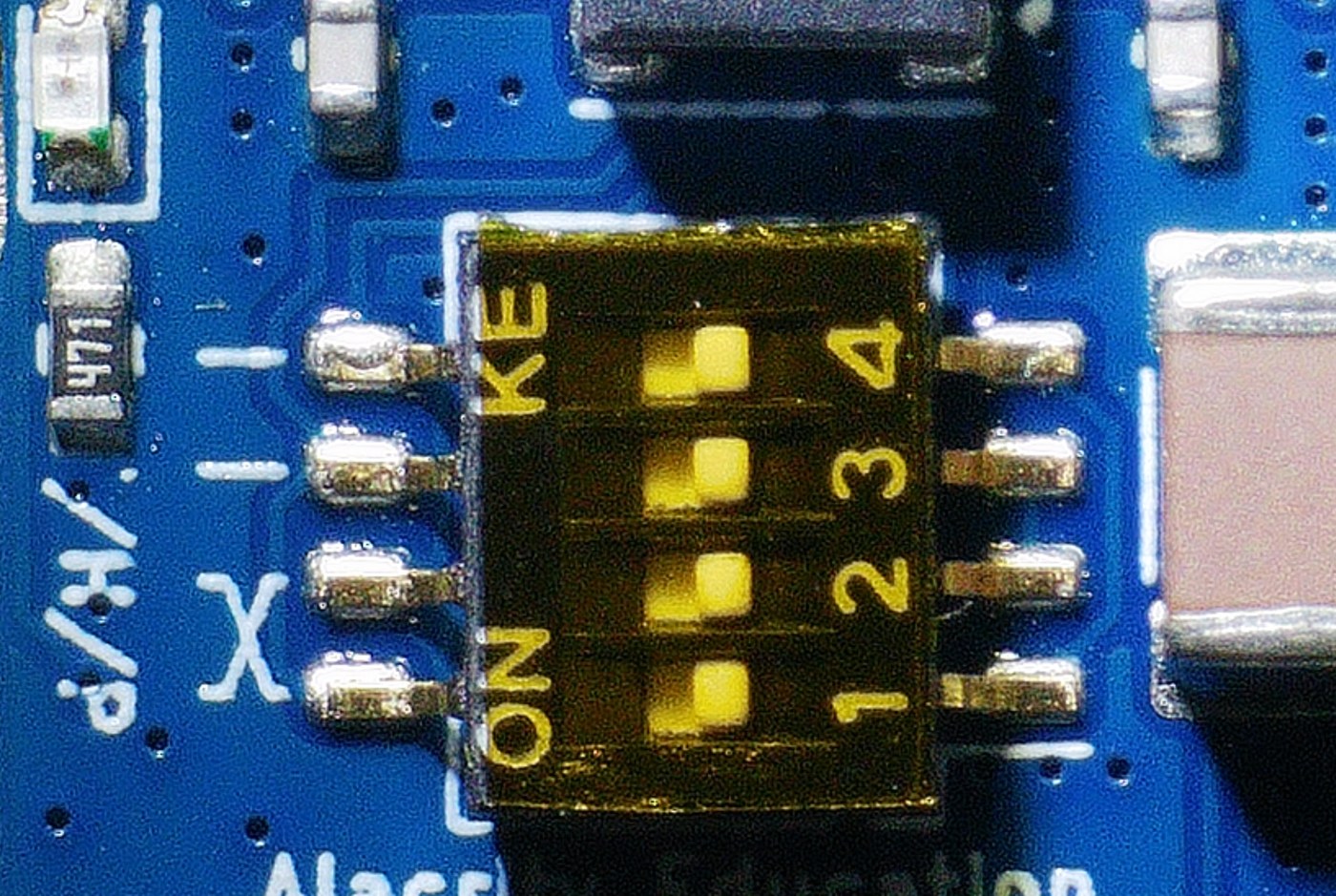
The silkscreen next to the DIP switch shows the two settings:
- Straight (
||): the two switches next to||ON, the two next toXOFF. - Swapped (
X): the two switches next toXON, the two next to||OFF. The head's two RS485 lines are crossed.
Go by the silkscreen marks, not the numbers on the switch: the switch can be fitted either way round.
Use one pair at a time: turning on all four switches shorts the RS485 lines.
space 900x604
1 box 120,225 205,330 green
1 box 440,205 540,345 green
2 box 120,375 210,485 orange
2 box 440,355 540,500 orange
- Straight
||— both switches by||ON, both byXOFF - Swapped
X— both switches byXON, both by||OFF - Never turn on all four. ON = slide toward the ON side
LEDs
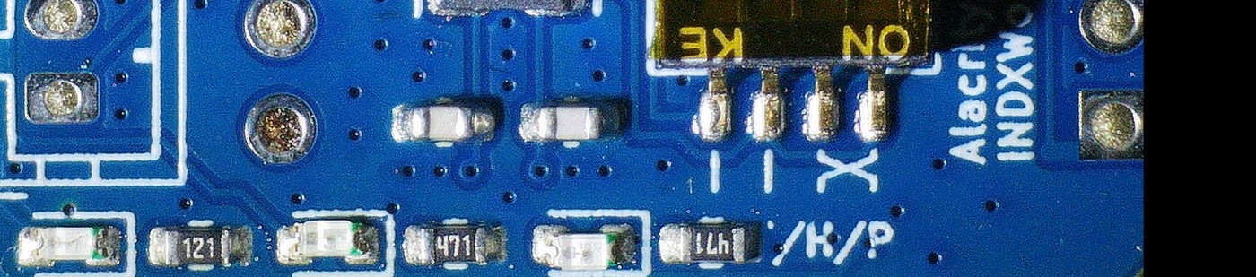
The silkscreen T/H/P names the three LEDs:
- T (blue): traffic, RS485 activity.
- H (red): head power, the switched 5V to the head is on.
- P (orange): board power.
space 900x199
1 box 15,155 90,195 blue
2 box 205,155 275,195 red
3 box 390,155 450,195 orange
  box 545,150 640,195 white
- T: traffic — RS485 activity, blue
- H: head power — 5 V to the head, red
- P: power — board power, orange
Options
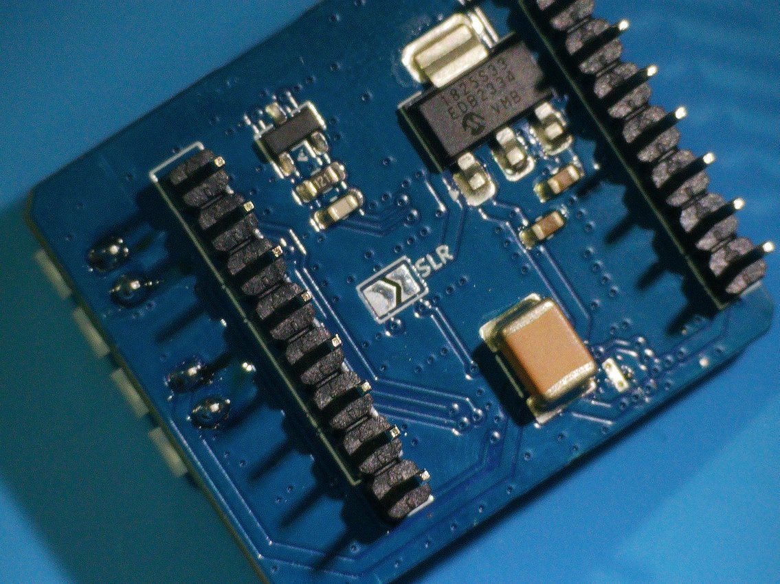
JP4(SLR, on the back) is a solder jumper, open by default. Closing it ties the STR485 slew-rate pin to 3.3V; see the STR485 datasheet.
Gallery
 |
 |
|---|---|
 |
 |
 |
 |
KliFan V1
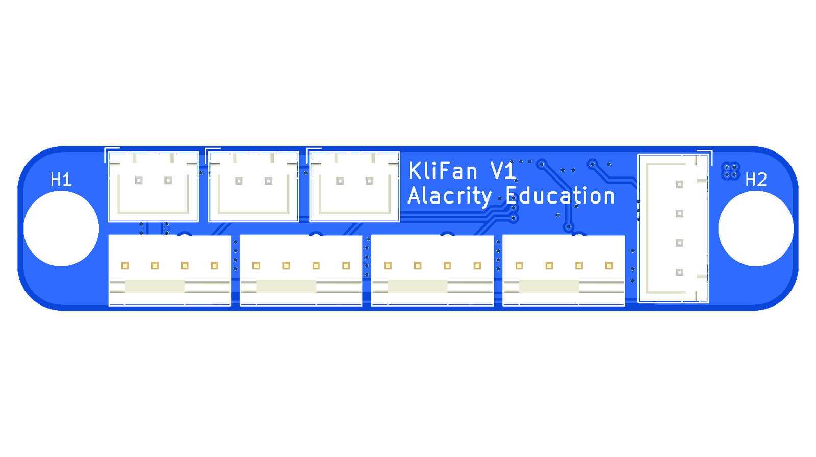
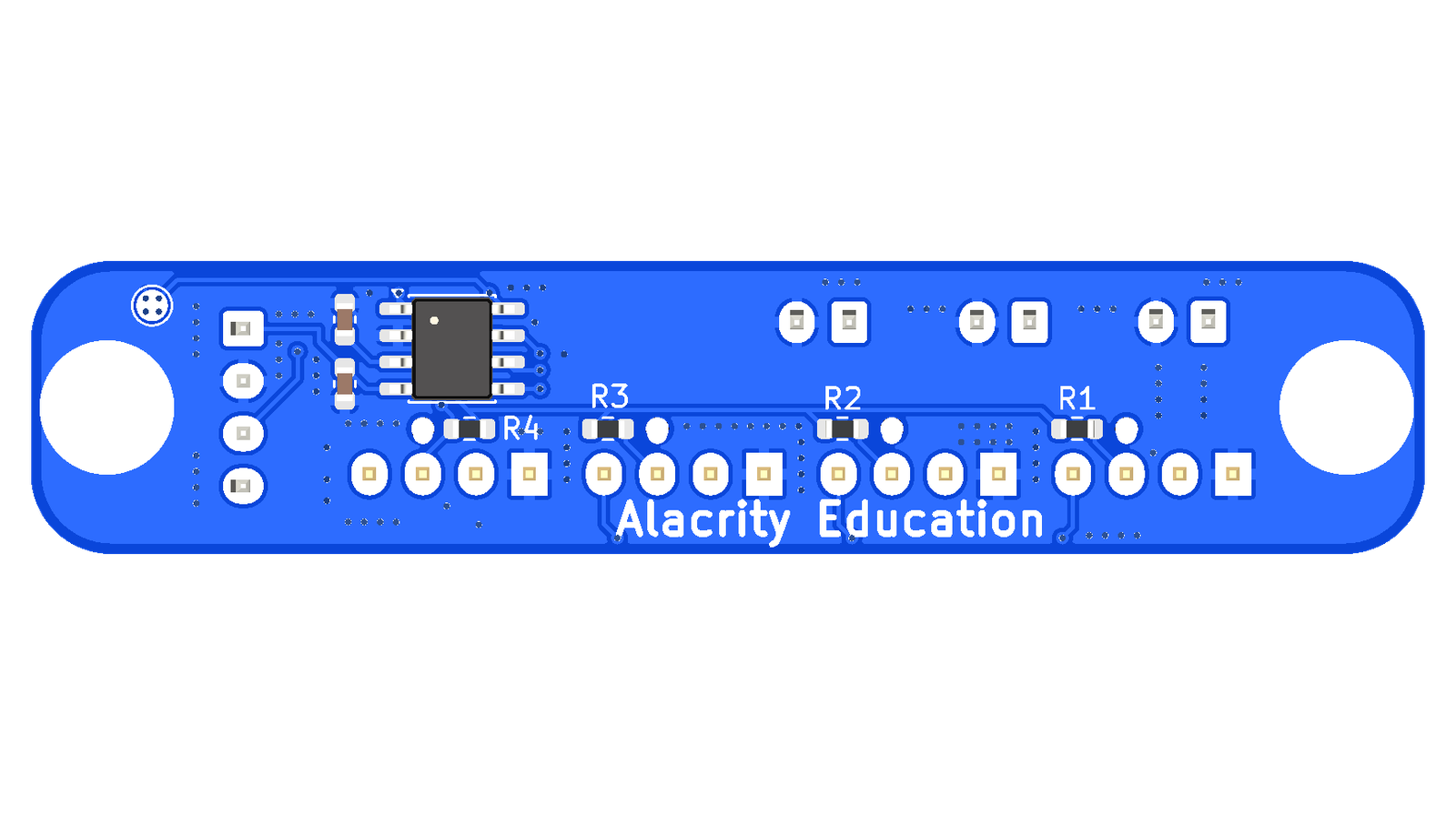
A fan hub for Klipper printers. One PWM signal from the motherboard drives four 4-pin PWM fans, and a tiny microcontroller (STM8S001J3) reads the four tach lines so the printer can watch the fans through a single endstop input. The board takes 12V through one of its three 2-pin headers; the other two take always-on 12V fans.
 |
 |
|---|
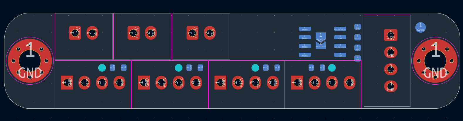
Pinout
J11: printer connection (JST-XH, 4-pin)
The vertical connector at the end of the board. It goes to the motherboard: pins 1-3 to an endstop port, pin 4 to a free digital output.
              +-------+
  +5V    1 ---| [■]   |      <-- endstop port, 5V
  GND    2 ---| (o)   |]     <-- endstop port, GND
  TACH   3 ---| (o)   |]     --> endstop port, signal  (tach_out)
  PWM    4 ---| (o)   |      <-- motherboard digital output pin (fan PWM)
              +-------+
                       ^
                       tab
Fan headers
The four 4-pin headers are PC-fan compatible: any standard 4-pin PWM PC fan plugs straight in. Their speed follows the PWM signal on J11 pin 4, and the microcontroller reads each fan's tach line.
The three 2-pin headers are standard 3D-printer 12V fan headers, all wired in parallel. One of them must be connected to an always-on 12V fan header on the motherboard, or directly to the 12V supply: this powers the whole board, including the 4-pin fans. J9 is marked SUPPLY for this, but any of the three works. The other two take always-on fans, which run at full speed whenever the board has 12V.
The mounting holes H1 and H2 are connected to GND.
Programming and options
TP1(SWIM) is the programming pad. It shares the STM8 pin with TACH4.JP1is a solder jumper, open by default. Closing it connects TACH1 straight to J11 pin 3, so the board can be used without the microcontroller.
Firmware
Not written yet.
PIPSU
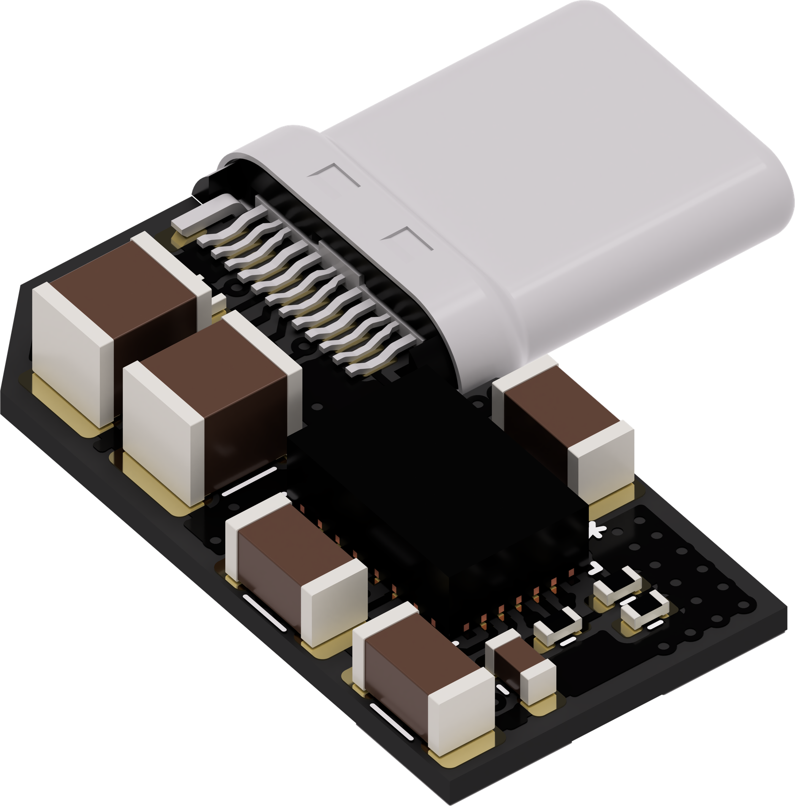
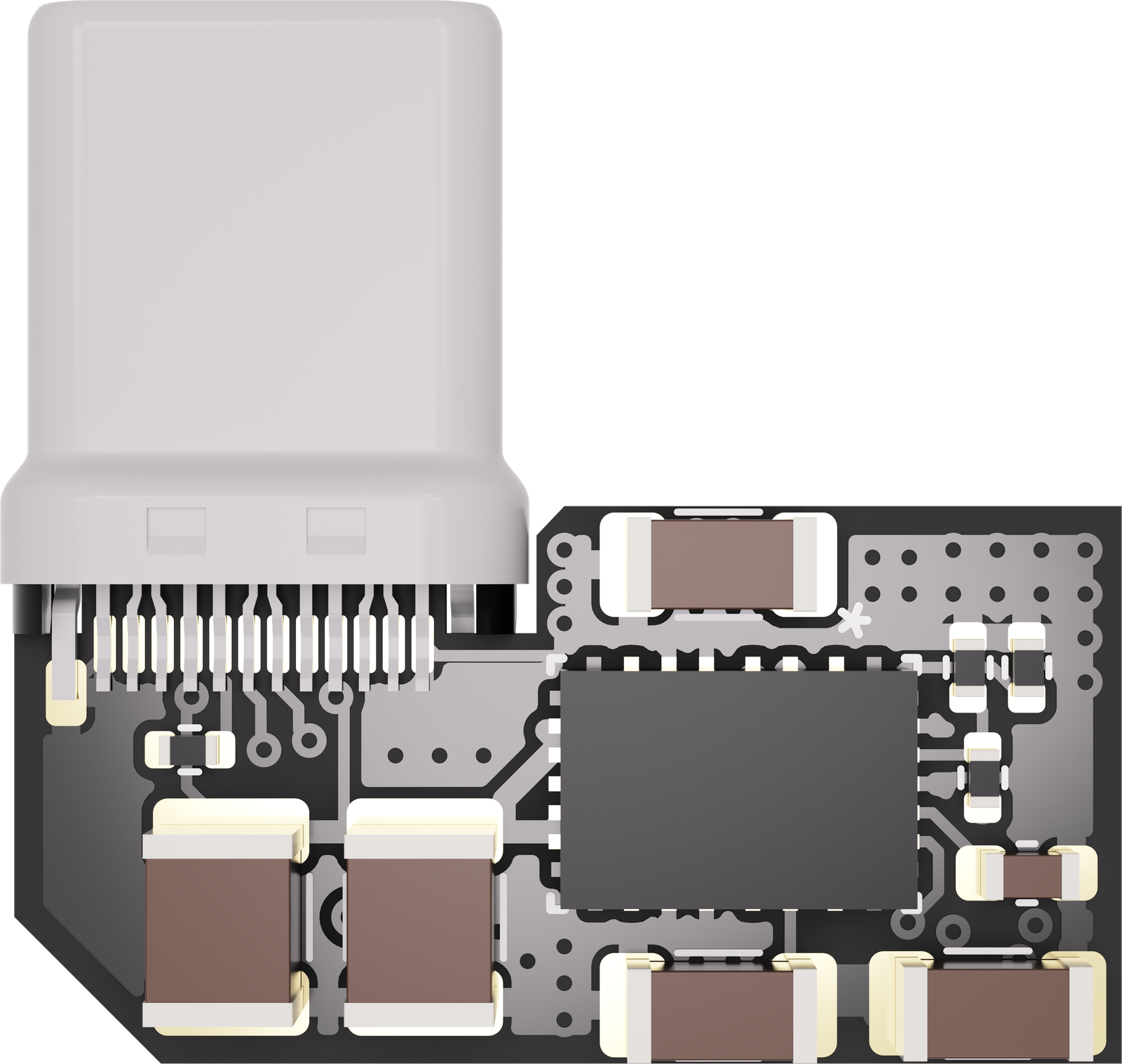
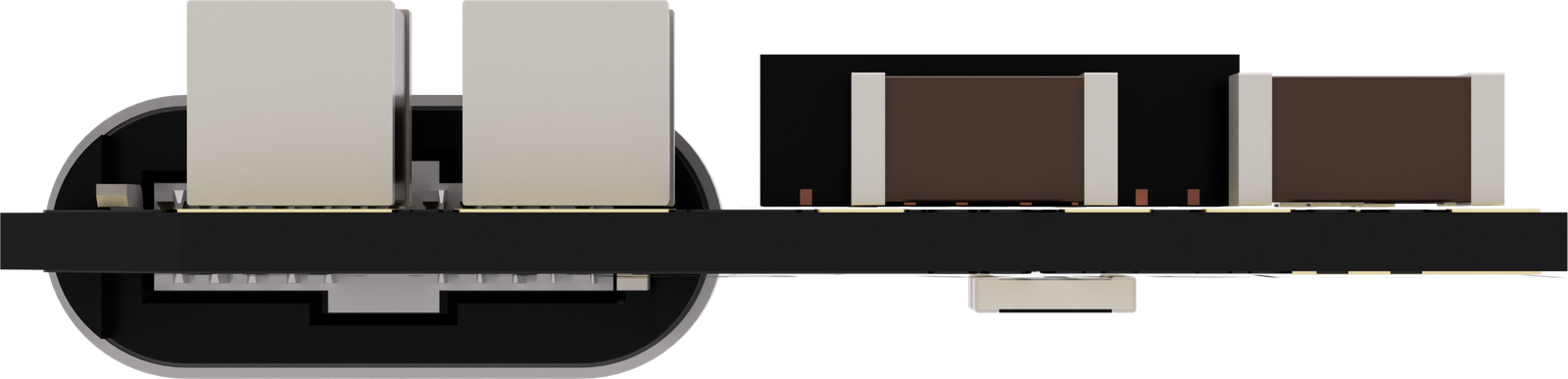
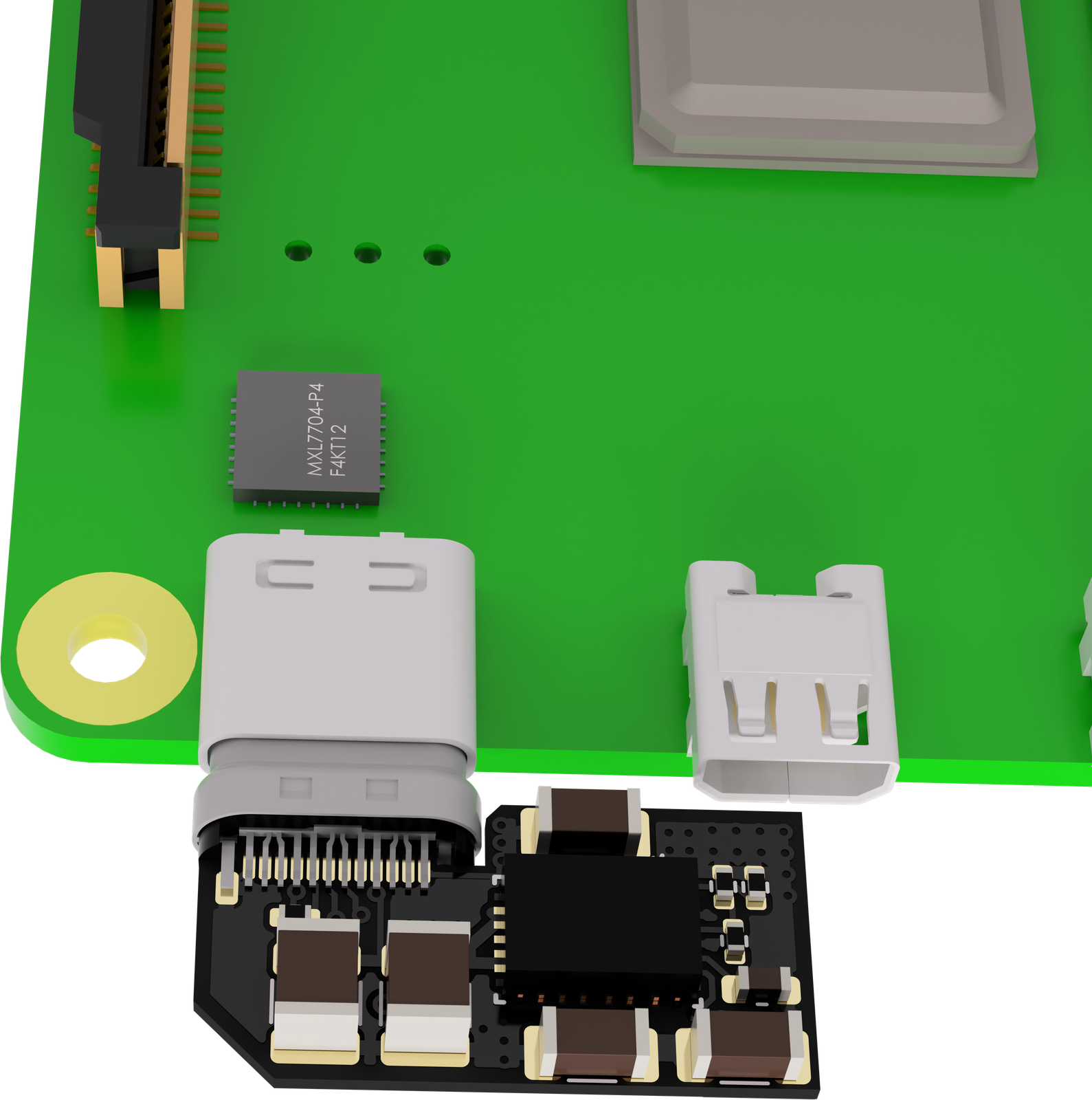
A tiny PSU for Raspberry Pi boards. It plugs straight into the Pi's USB-C port and supplies 5V, up to 3A, from the printer's 24V supply line (it accepts 8-30V). We built it to take the Raspberry Pi's power draw off the mainboard's regulator and use a more stable supply instead.
 |
 |
 |
|---|
The board uses TI's TPSM63603, an ultra-integrated power module, to keep the footprint very small. Its high efficiency keeps the temperature manageable at full load, on a very small board with completely passive cooling.
Connections
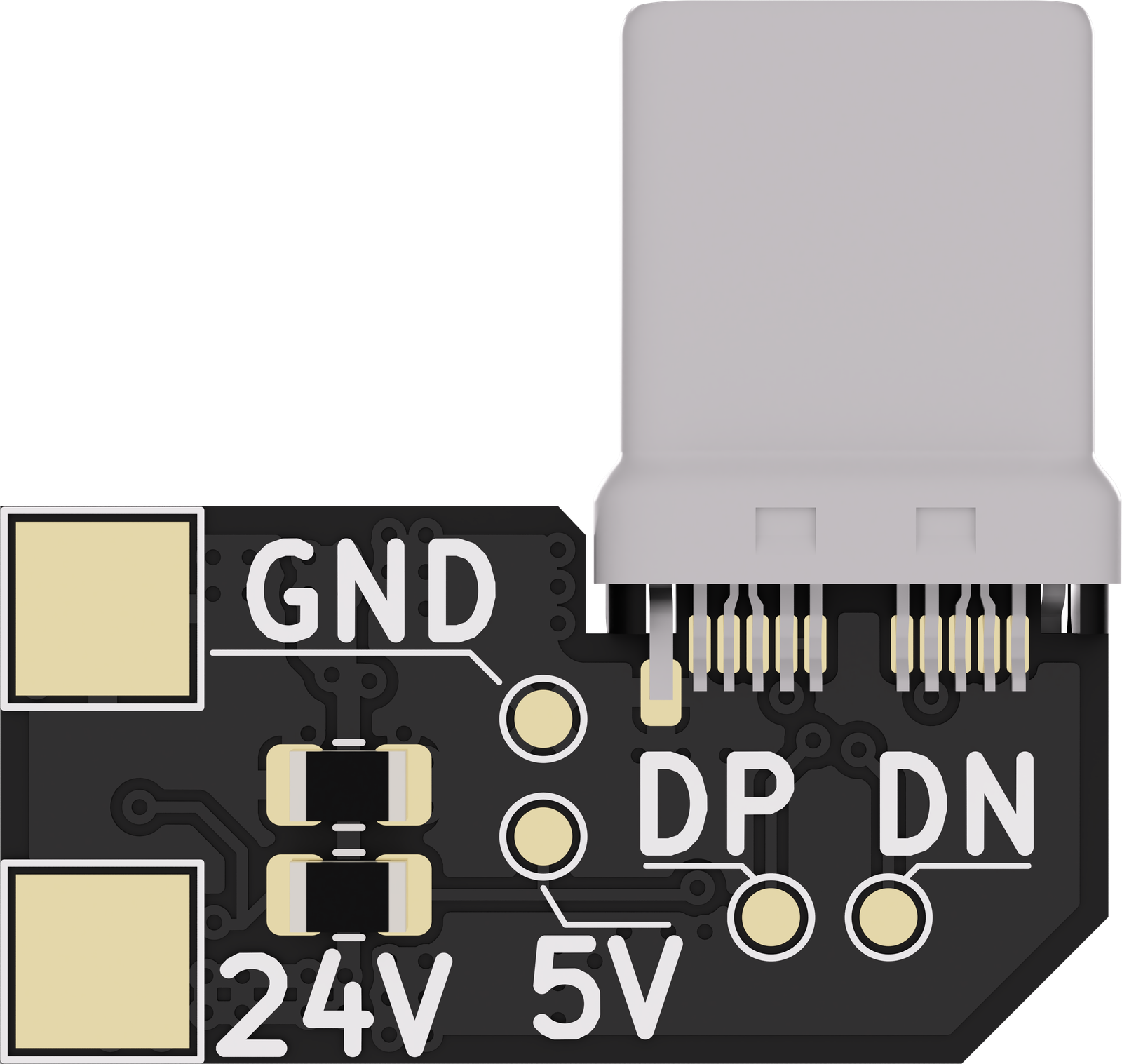
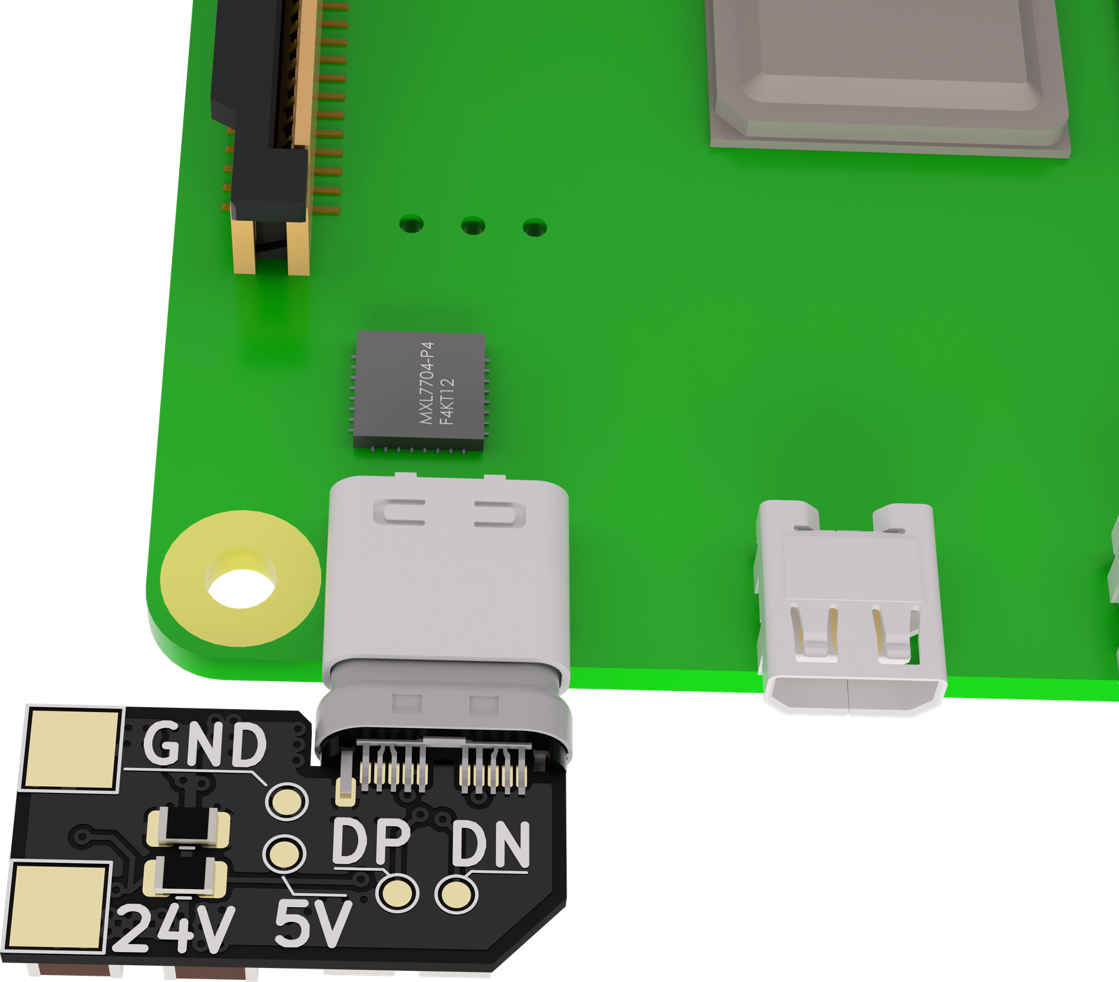
All the pads are on the back of the board:
- 24V and GND (large pads): the input from the printer's 24V supply (8-30V).
- 5V and GND (small pads): 5V out, for powering peripherals.
- DP and DN: the USB 2.0 data lines of the USB-C plug, for connecting a USB device to the Pi.
The USB-C plug advertises a 3A source to the Pi on its CC line.
 |
 |
|---|